A resistive network is a circuit composed solely of resistors, voltage sources, and current sources. The primary goal of analysis is to determine the voltage across and current through every element.
Ohm’s Law
The relationship between voltage (


- Unit: Ohms (
)
- Power Dissipation:
(measured in Watts)
Kirchhoff’s Laws
- Kirchhoff’s Current Law (KCL): The algebraic sum of currents entering a node is zero.
- Kirchhoff’s Voltage Law (KVL): The algebraic sum of all voltages around any closed loop in a circuit is zero.


Resistor Combinations
To simplify complex circuits, we combine resistors into equivalent resistances (
| Configuration | Formula | Characteristics |
| Series |  | Same current flows through each resistor. |
| Parallel |  | Same voltage across each resistor. |
Voltage and Current Division
These rules allow for quick calculations without solving full systems of equations.
Voltage Divider (Series)
Used to find the voltage across a specific resistor in a series string:

Current Divider (Parallel)
Assume there are two resistors 


Network Analysis Techniques
Nodal Analysis
Based on KCL. You select a reference node (ground) and solve for the voltages at the remaining nodes.
- Best for: Circuits with many parallel branches and current sources.
Mesh Analysis
Based on KVL. You assign “mesh currents” to the smallest loops in a circuit and solve for them.
- Best for: Planar circuits with many series components and voltage sources.
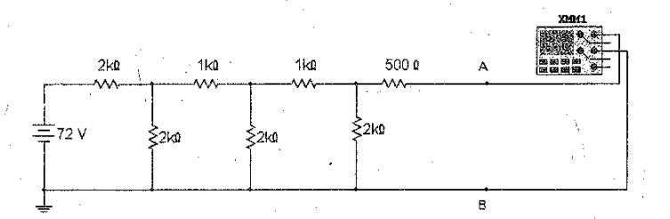
Problem: Find the total current (


Step 1: Simplify the parallel branch (

Step 2: Find the equivalent resistance (

Step 3: Apply Ohm’s Law

Key Theorems for Simplification
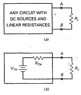
- Thevenin’s Theorem: Any linear circuit can be replaced by an equivalent voltage source (
) in series with a resistor (
).
- Norton’s Theorem: Any linear circuit can be replaced by an equivalent current source (
) in parallel with a resistor (
).
- Maximum Power Transfer: Maximum power is delivered to a load when the load resistance (
) equals the Thevenin resistance (
 . Check this by calculating
  and
and  . Source: Electronic Principles, Albert Malvino